cavitatingFoam – barotropicCompressibilityModel (v1812)

Last Updated: June 9, 2019

The cavitatingFoam is a transient cavitation solver based on the homogeneous equilibrium model (HEM) from which the compressibility of the liquid/vapour ‘mixture’ is obtained, whose density varies from liquid density to vapor one according to the chosen barotropic equation of state.

Compressibility and speed of sound

\begin{align}
\frac{D \rho}{Dt} = \psi \frac{Dp}{Dt} \tag{1} \label{eq:eos}
\end{align}

\begin{align}
\psi = \rho \beta_s \tag{2} \label{eq:psi}
\end{align}

  • \(\rho\): density
  • \(p\): pressure
  • \(\beta_s\): isentropic compressibility

The definition of the isentropic compressibility can be deformed in the following way:
\begin{align}
\beta_s &\equiv -\frac{1}{V} \left( \frac{\partial V}{\partial p} \right)_s \tag{3} \label{eq:betas} \\
&= -\frac{1}{V} \left(\frac{\partial V}{\partial \rho} \frac{\partial \rho}{\partial p} \right)_s \\
&= \rho \frac{1}{\rho^2} \left(\frac{\partial \rho}{\partial p} \right)_s \\
&= \frac{1}{\rho c^2}
\end{align}
where \(c\) is the speed of sound. We can substitute this expression for \(\beta_s\) in \eqref{eq:psi}, obtaining the following expression:
\begin{align}
\psi = \frac{1}{c^2}. \tag{4} \label{eq:psi-sos}
\end{align}
The compressibility of the mixture equals to the reciprocal of the square of the speed of sound.

We can specify a compressibility function \(\psi\) that defines the coupling between the density and pressure in the thermophysicalProperties file.

barotropicCompressibilityModel

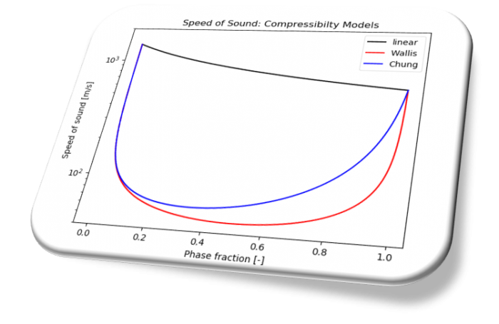
The following three models for \(\psi\) are available in OpenFOAM v1812.

  • linear
  • Chung
  • Wallis

  • psiv: compressibility \(\psi\) of the vapor phase
  • psil: compressibility \(\psi\) of the liquid phase
  • pSat: saturation pressure
  • rhovSat: density of vapor at saturation point
  • rholSat: density of liquid at saturation point

The expressions of the speed of sound \(c\) in the liquid/vapour mixture are different according to the selected function.

linear

\begin{align}
\psi = \gamma \psi_v + \left(1 – \gamma \right)\psi_l \tag{5} \label{eq:linear}
\end{align}

Chung

\begin{align}
s_{fa} = \sqrt{ \frac{\frac{\rho_{v, Sat}}{\psi_v}}{\left( 1- \gamma \right)\frac{\rho_{v, Sat}}{\psi_v} + \gamma \frac{\rho_{l, Sat}}{\psi_l}} } \tag{6} \label{eq:chung-sfa}
\end{align}
\begin{align}
\psi = \left( \left( \frac{1 – \gamma}{\sqrt{\psi_v}} + \gamma \frac{s_{fa}}{\sqrt{\psi_l}} \right)\frac{\sqrt{\psi_v \psi_l}}{s_{fa}} \right)^2 \tag{7} \label{eq:chung}
\end{align}

Wallis

\begin{align}
\psi = \left( \gamma \rho_{v, Sat} + \left( 1 – \gamma \right)\rho_{l, Sat} \right)
\left( \gamma \frac{\psi_v}{\rho_{v, Sat}} + \left( 1 – \gamma \right)\frac{\psi_l}{\rho_{l, Sat}} \right) \tag{8} \label{eq:wallis}
\end{align}
\begin{align}
\frac{\psi}{\gamma \rho_{v, Sat} + \left( 1 – \gamma \right)\rho_{l, Sat}} = \gamma \frac{\psi_v}{\rho_{v, Sat}} + \left( 1 – \gamma \right)\frac{\psi_l}{\rho_{l, Sat}} \tag{8′} \label{eq:wallis2}
\end{align}

References

[1] Christopher Earls Brennen, Fundamentals of Multiphase Flow. Cambridge University Press (2005)
twoPhaseEulerFoam – Diameter Model (v1812)

constant

Constant dispersed-phase particle diameter model.

isothermal

Isothermal dispersed-phase particle diameter model.
\begin{align}
p \times \frac{4}{3} \pi \left( \frac{d}{2} \right)^3 &= p_0 \times \frac{4}{3} \pi \left( \frac{d_0}{2} \right)^3 \\
d &= d_0 \left( \frac{p_0}{p} \right)^{1/3} \tag{1} \label{eq:levmdiffusion}
\end{align}

IATE

IATE (Interfacial Area Transport Equation) bubble diameter model.
Solves for the interfacial curvature per unit volume of the phase rather than interfacial area per unit volume to avoid stability issues relating to the consistency requirements between the phase fraction and interfacial area per unit volume.

The following bubble interaction mechanisms are considered in this model.

    • wakeEntrainmentCoalescence
      Bubble coalescence by wake entrainment
    • randomCoalescence
      Bubble coalescence by random collision
    • turbulentBreakUp
      Bubble break-up due to the impact of turbulent eddies
      \begin{align}
      \phi_{TI} = \frac{C_{ti}}{3} \frac{U_t}{d} \sqrt{1 – \frac{We_{Cr}}{We}} e^{-\frac{We_{Cr}}{We}}
      \end{align}

      • \(We\): Weber number [-]
      • \(U_t\): Turbulent fluctuation velocity [m/s]

twoPhaseEulerFoam – phaseProperties


In solving two-phase flow problems, we can use a variety of simulation techniques, such as Eulerian-Eulerian, Eulerian-Lagrangian methods, Volume of Fluid (VOF) method and homogeneous equilibrium model (HEM).

In this page, I will organize information on the physical models available in twoPhaseEulerFoam, an Eulerian-Eulerian solver available in OpenFOAM.

I will add descriptions of each model.


Selected OpenFOAM version:

drag model
  • Ergun
  • Gibilaro
  • GidaspowErgunWenYu
  • GidaspowSchillerNaumann
  • IshiiZuber
  • Lain
  • SchillerNaumann
  • SyamlalOBrien
  • TomiyamaAnalytic
  • TomiyamaCorrelated
  • WenYu
  • segregated

Read more

lift model
  • LegendreMagnaudet
  • Moraga
  • Tomiyama
  • constantCoefficient
  • none
heatTransfer model
  • RanzMarshall
  • spherical
turbulentDispersion model
  • Burns
  • Gosman
  • LopezDeBertodano
  • constantCoefficient
  • none
virtualMass model
  • Lamb
  • constantCoefficient
  • none
aspectRatio model
  • Tomiyama
  • VakhrushevEfremov
  • Wellek
  • constant
wallLubrication model
  • Antal
  • Frank
  • Tomiyama
  • none
diameter model
  • constant
  • isothermal
  • IATE

Read more


Diffusion Term of the N-S Equations Part1


The mathematical expressions of the viscous stress differ between Newtonian fluids and non-Newtonian fluids, so do those of the diffusion term. In this post, we consider only Newtonian fluids, such as air and water.

Many turbulence models treat the effects of the turbulence as augmentation of mixing or diffusion, but the modeled expression differs depending on the turbulence models, such as linear eddy-viscosity, non-linear eddy viscosity and Reynolds-stress transport models.

We’ll start by running through mathematical expressions of the diffusion term and find out how these are implemented in OpenFOAM.

Diffusion term (Newtonian fluids)

For Newtonian fluids the ratio of the shear stress to the shear rate is constant and the diffusion term of the Navier-Stokes equations are given by:

\begin{equation}
\nabla \cdot \left( \mu \left( \nabla \boldsymbol{u} + (\nabla \boldsymbol{u})^T \right) -\frac{2}{3}\mu (\nabla \cdot \boldsymbol{u}) \boldsymbol{I} \right), \tag{1} \label{eq:newtondiffusion}
\end{equation}
where \(\boldsymbol{u}\) is the velocity field, \(\mu\) is the molecular viscosity and \(\boldsymbol{I}\) is the identity tensor.

In the case of laminar flows and Direct Numerical Simulations (DNS) of turbulent flows, this expression is used.

When we solve turbulent flows with turbulence models, the expression of the diffusion term changes from Eq. \eqref{eq:newtondiffusion} according to the model we choose. If we use the linear eddy-viscosity models of Reynolds-averaged Navier-Stokes (RANS), such as k-\(\epsilon\) and k-\(\omega\) SST models, the Reynolds stress is modeled with the following expression:

\begin{equation}
-\rho\overline{\boldsymbol{u}\boldsymbol{u}} = \mu_t \left( \nabla \overline{\boldsymbol{u}} + (\nabla \overline{\boldsymbol{u}})^T \right) -\frac{2}{3}\rho k \boldsymbol{I}, \tag{2} \label{eq:BoussinesqApprox}
\end{equation}

and the diffusion term is expressed as:

\begin{align}
&\nabla \cdot \left( \mu \left( \nabla \overline{\boldsymbol{u}} + (\nabla \overline{\boldsymbol{u}})^T \right) -\frac{2}{3}\mu (\nabla \cdot \overline{\boldsymbol{u}}) \boldsymbol{I} -\rho\overline{\boldsymbol{u}\boldsymbol{u}} \right) \\
=& \nabla \cdot \left( (\mu + \mu_t) \left( \nabla \overline{\boldsymbol{u}} + (\nabla \overline{\boldsymbol{u}})^T \right) -\frac{2}{3}\mu (\nabla \cdot \overline{\boldsymbol{u}}) \boldsymbol{I} – \frac{2}{3}\rho k \boldsymbol{I} \right) \\
=& \nabla \cdot \left( \mu_{eff} \left( \nabla \overline{\boldsymbol{u}} + (\nabla \overline{\boldsymbol{u}})^T \right) -\frac{2}{3}\mu (\nabla \cdot \overline{\boldsymbol{u}}) \boldsymbol{I} \right) – \nabla \cdot \left( \frac{2}{3}\rho k \boldsymbol{I} \right), \tag{3} \label{eq:levmdiffusion}
\end{align}
where \(\overline{\boldsymbol{u}}\) is the ensemble-averaged velocity field, \(k\) is the turbulence energy, \(\rho\) is the density and the effective viscosity \(\mu_{eff}\) is the sum of the molecular and turbulent eddy viscosity \(\mu_t\).

If the flow is incompressible, the expression reduces to the following one because of the continuity equation \(\nabla \cdot \overline{\boldsymbol{u}} = 0\):
\begin{equation}
\nabla \cdot \left( \mu_{eff} \left( \nabla \overline{\boldsymbol{u}} + (\nabla \overline{\boldsymbol{u}})^T \right) \right) – \nabla \cdot \left( \frac{2}{3}\rho k \boldsymbol{I} \right). \tag{4} \label{eq:incompdiffusion}
\end{equation}

If turbulence models of the eddy-viscosity type is used, the effects of fluctuating turbulent flows are expressed as augmentation of the diffusion as can be seen from Eq. \eqref{eq:levmdiffusion}.

We are all set!
Let’s look into how the diffusion term is handled in OpenFOAM 🙂

Implementation in OpenFOAM

If we have a quick look at UEqn.H file of rhoPimpleFoam, a transient compressible flow solver, we can find turbulence->divDevRhoReff(U) in it. It corresponds to the diffusion term.

We can find its definitions in different files depending on the types of the turbulence models. In the case of linear eddy viscosity models, it is defined in linearViscousStress.C file.

We can find a tiny difference by comparing it with Eq. \eqref{eq:levmdiffusion}:
l.10
\begin{equation}
\nabla \cdot \left( \mu_{eff} \left( (\nabla \overline{\boldsymbol{u}})^T -\frac{2}{3} (\nabla \cdot \overline{\boldsymbol{u}}) \boldsymbol{I} \right) \right), \tag{5} \label{eq:levmdiffusion1}
\end{equation}
l.11
\begin{equation}
\nabla \cdot \left( \mu_{eff} \nabla \overline{\boldsymbol{u}} \right). \tag{6} \label{eq:levmdiffusion2}
\end{equation}

The remaining term \(- \nabla \cdot \left( \frac{2}{3}\rho k \boldsymbol{I} \right)\) is included in the pressure gradient term.

In the next post, we’ll look into non-linear eddy viscosity models and Reynolds-stress transport models.

Thank you for taking the time to read all of my post!

Temperature calculation from energy variables in OpenFOAM


The energy conservation equation is expressed in terms of internal energy \(e\) or enthalpy \(h\) in OpenFOAM and the temperature field is calculated from these solution variables. More precisely, we can specify the energy variable in the energy entry in the thermophysicalProperties file and the available options are the followings:

  • specific sensible enthalpy \(h {\rm [J/kg]}\) (sensibleEnthalpy)
  • specific sensible internal energy \(e {\rm [J/kg]}\) (sensibleInternalEnergy)

If we select the hePsiThermo thermophysical model, the temperature field \(T\) is calculated from the solved energy variable in the following function, where the compressibility \(\psi\), dynamic viscosity \(\mu\) and thermal diffusivity \(\alpha\) are also calculated.

Source Code

The calculation procedure of the temperature field depends on the selected energy variable, so the following THE function accordingly switches the called method.

If we choose the sensible enthalpy as the energy variable, the following THs function is called to calculate the temperature from the sensible enthalpy.

The calculation of the temperature is done iteratively using the Newton-Raphson method.

If the specific heat capacity at constant pressure \(c_p\) is expressed in the form of temperature polynomial function (hPolynomial)
\begin{equation}
c_p(T) = \sum_{i=0}^7 c_i T^i, \tag{1}
\end{equation}
the temperature in the j-th cell \(T_j\) is calculated from the following equation
\begin{equation}
\displaystyle \int_{T_{std}}^{T_j} \left( \sum_{i=0}^7 c_i T^i \right) dT = h_j, \tag{2}
\end{equation}
where \(h_j\) is the sensible enthalpy value in the j-th cell. In general the equation will be nonlinear, the iterative solution technique is implemented.

Compressible Flow Solvers

The above function calculate() is called by rhoPimpleFoam, rhoSimpleFoam and sonicFoam etc. from the line “thermo.correct()” after solving the energy conservation equation EEqn:

After updating the compressibility field \(\psi\), the pressure Poisson equation pEqn is constructed and solved.

The density field \(\rho\) is calculated with updated pressure and compressibility fields.

Summary
Energy variable Function used to calculate temperature
sensible enthalpy THs
absolute enthalpy THa
sensible internal energy TEs
absolute internal energy TEa

Study with great curiosity and let’s see the physical phenomena from a HIGHER point of view!

Tensor Operations in OpenFOAM

Last Updated: May 5, 2019

The gradient of the velocity field is a strain-rate tensor field, that is, a second rank tensor field. It appears in the diffusion term of the Navier-Stokes equation.

A second rank tensor has nine components and can be expressed as a 3×3 matrix as shown in the above image.

In this blog post, I will pick out some typical tensor operations and give brief explanations of them with some usage examples in OpenFOAM.

Keywords
strain rate tensor, vorticity tensor, Q-criterion, Hodge dual

Gradient of a Vector Field | fvc::grad(u)

The gradient of a velocity vector \(\boldsymbol{u}\) returns a velocity gradient tensor (second rank tensor).
\begin{eqnarray}
\nabla \boldsymbol{u} &\equiv& \partial_{i} u_j \\
&=& \left(
\begin{matrix}
\partial u_1/\partial x_1 & \partial u_2/\partial x_1 & \partial u_3/\partial x_1 \\
\partial u_1/\partial x_2 & \partial u_2/\partial x_2 & \partial u_3/\partial x_2 \\
\partial u_1/\partial x_3 & \partial u_2/\partial x_3 & \partial u_3/\partial x_3
\end{matrix} \right)
\end{eqnarray}

Symmetric Part of a Second Rank Tensor | symm(T)

\begin{eqnarray}
{\rm symm}(\boldsymbol{T}) &\equiv& \frac{1}{2} (\boldsymbol{T} + \boldsymbol{T}^T) \\
&=& \frac{1}{2} \left(
\begin{matrix}
2T_{11} & T_{12} + T_{21} & T_{13} + T_{31} \\
T_{21} + T_{12} & 2T_{22} & T_{23} + T_{32} \\
T_{31} + T_{13} & T_{32} + T_{23} & 2T_{33}
\end{matrix} \right)
\end{eqnarray}

Twice the Symmetric Part of a Second Rank Tensor | twoSymm(T)

\begin{eqnarray}
{\rm twoSymm}(\boldsymbol{T}) &\equiv& \boldsymbol{T} + \boldsymbol{T}^T \\
&=& \left(
\begin{matrix}
2T_{11} & T_{12} + T_{21} & T_{13} + T_{31} \\
T_{21} + T_{12} & 2T_{22} & T_{23} + T_{32} \\
T_{31} + T_{13} & T_{32} + T_{23} & 2T_{33}
\end{matrix} \right)
\end{eqnarray}

Skew-symmetric Part of a Second Rank Tensor | skew(T)

\begin{eqnarray}
{\rm skew}(\boldsymbol{T}) &\equiv& \frac{1}{2} (\boldsymbol{T} – \boldsymbol{T}^T) \\
&=& \frac{1}{2} \left(
\begin{matrix}
0 & T_{12} – T_{21} & T_{13} – T_{31} \\
T_{21} – T_{12} & 0 & T_{23} – T_{32} \\
T_{31} – T_{13} & T_{32} – T_{23} & 0
\end{matrix} \right)
\end{eqnarray}

The symm and skew operations of the velocity gradient tensor field frequently appear in the source code. The following is a typical example.

In the above code, the symmetric and antisymmetric parts of the velocity gradient tensor \(\partial u_j/\partial x_i\) are defined as follows:
\begin{eqnarray}
S_{ij} &=& \frac{1}{2} \left( \frac{\partial u_j}{\partial x_i} + \frac{\partial u_i}{\partial x_j} \right), \\
\Omega_{ij} &=& \frac{1}{2} \left( \frac{\partial u_j}{\partial x_i} – \frac{\partial u_i}{\partial x_j} \right),
\end{eqnarray}
where \(S_{ij}\) is the strain rate tensor and \(-\Omega_{ij}\) is the vorticity (spin) tensor.

Hodge Dual | *T

\begin{equation}
*T = \left( T_{23},\;-T_{13},\;T_{12} \right)
\end{equation}

The vorticity vector \(\boldsymbol{\omega}\) is calculated as the Hodge dual of the skew-symmetric part of the velocity gradient tensor.
\begin{eqnarray}
\boldsymbol{\omega} &=& 2 \times \left( * \Omega_{ij} \right) \\
&=& 2 \times \left( \Omega_{23},\;-\Omega_{13},\;\Omega_{12} \right) \\
&=& \left( \frac{\partial u_3}{\partial x_2}-\frac{\partial u_2}{\partial x_3},\;\frac{\partial u_1}{\partial x_3}-\frac{\partial u_3}{\partial x_1},\;\frac{\partial u_2}{\partial x_1}-\frac{\partial u_1}{\partial x_2} \right)
\end{eqnarray}

The operator * in front of the skew is the Hodge dual operator.

Inner Product of Two Second Rank Tensors | T & S

\begin{equation}
P_{ij} = T_{ik} S_{kj}
\end{equation}

Double Inner Product of Two Second Rank Tensors | T && S

\begin{align}
s = T_{ij}S_{ij} &= T_{11}S_{11} + T_{12}S_{12} + T_{13}S_{13} \\
&+ T_{21}S_{21} + T_{22}S_{22} + T_{23}S_{23} \\
&+ T_{31}S_{31} + T_{32}S_{32} + T_{33}S_{33}
\end{align}

Trace of a Second Rank Tensor | tr(T)

\begin{equation}
{\rm tr}(\boldsymbol{T}) \equiv T_{11} + T_{22} + T_{33} = \boldsymbol{T} {\rm \&}{\rm \&} \boldsymbol{I}
\end{equation}

The Q-criterion can be used to identify vortex cores:
\begin{align}
Q &= \frac{1}{2} \left[ (\nabla \cdot \boldsymbol{u})^2 – {\rm tr}(\nabla \boldsymbol{u}^2)\right] \\
&= \frac{1}{2} \left[ (\nabla \cdot \boldsymbol{u})^2 + \Omega_{ij}\Omega_{ij} – S_{ij}S_{ij} \right].
\end{align}
For incompressible flows, it can be simplified as follows:
\begin{equation}
Q = \frac{1}{2} \left[ \Omega_{ij}\Omega_{ij} – S_{ij}S_{ij} \right].
\end{equation}

References

[1] OpenFOAM Programmer’s Guide
[2] CFD Direct | Tensor Mathematics

Recent changes in the basics of the OpenFOAM solvers

constrainHbyA

Comment by Henry G. Weller:

The boundary conditions of HbyA are now constrained by the new “constrainHbyA” function which applies the velocity boundary values for patches for which the velocity cannot be modified by assignment and pressure extrapolation is not specified via the new
“fixedFluxExtrapolatedPressureFvPatchScalarField”.

The member function assignable() is defined in the abstract base class of boundary conditions (fvPatchField):

It is overridden in the basic boundary condition classes (fixedValue, mixed, directionMixed and sliced):

fvc::flux and dotInterpolate

Comment by Henry G. Weller:

surfaceInterpolationScheme: Added dotInterpolate member-function

dotInterpolate interpolates the field and “dots” the resulting face-values with the vector field provided which removes the need to create a temporary field for the interpolate. This reduces the peak storage of OpenFOAM caused by the divergence of the gradient of vector fields, improves memory management and under some conditions decreases run-time.

This development is based on a patch contributed by Paul Edwards, Intel.

constrainPressure

In the case of compressible flow, the following relation \eqref{eq:1} holds for the velocity on the face:
\begin{equation}
\rho \boldsymbol{U}_f \cdot \boldsymbol{S}_f = \left(\frac{\rho \boldsymbol{H}}{A_p}\right)_f \cdot \boldsymbol{S}_f\;-\;\left(\frac{\rho}{A_p}\right)_f (\nabla p)_f \cdot \boldsymbol{S}_f. \tag{1} \label{eq:1}
\end{equation}
Thus
\begin{equation}
(\nabla p)_f \cdot \boldsymbol{n}_f = \frac{1}{|\boldsymbol{S}_f|\left(\frac{\rho}{A_p}\right)_f} \left(\left(\frac{\rho \boldsymbol{H}}{A_p}\right)_f \cdot \boldsymbol{S}_f\;-\;\rho \boldsymbol{U}_f \cdot \boldsymbol{S}_f \right). \tag{2} \label{eq:2}
\end{equation}
The fixedFluxPressure boundary condition calculates the boundary normal gradient of the pressure field using the Eq. \eqref{eq:2} so that the boundary fluxes satisfy the Eq. \eqref{eq:1}.

Introduction to laplacianFoam and simple validation calculation


In this blog post, I will try to give a description of the governing equation of the laplacianFoam in OpenFOAM that solves a simple Laplace equation, e.g. for thermal diffusion in a solid.

Governing Equation

The heat conduction equation is given by the following equation:

\begin{align}
\frac{\partial T}{\partial t} = \frac{1}{\rho c_p} \nabla \cdot \left(k \nabla T\right) + \frac{q}{\rho c_p}, \tag{1} \label{eq:conductionEqn}
\end{align}

where \(T\;{\rm [ K]}\) is the absolute temperature field, \(\rho\;{\rm [kg/m^3]}\) is the density field, \(q\;{\rm [W/m^3]}\) is the rate of energy generation per unit volume, \(k\;{\rm [W/(m\cdot K)]}\) is the thermal conductivity and \(c_p\;{\rm [J/(kg\cdot K)]}\) is the specific heat at constant pressure.

If the heat capacity \(\rho c_p\) is spatially uniform, the Eq. \eqref{eq:conductionEqn} can be transformed into the following form irrespective of whether the thermal conductivity \(k\) is spatially uniform or not:

\begin{align}
\frac{\partial T}{\partial t} = \nabla \cdot \left(\alpha \nabla T\right) + \frac{q}{\rho c_p}, \tag{2} \label{eq:conductionEqn2}
\end{align}

where \(\alpha = k/\rho c_p\;{\rm [m^2/s]}\) is the thermal diffusivity.

The laplacianFoam (in OpenFOAM-4.x and earlier versions) doesn’t consider the heat generation and the implemented equation is

\begin{align}
\frac{\partial T}{\partial t} = \nabla \cdot \left(\alpha \nabla T\right), \tag{3} \label{eq:laplacianFoam}
\end{align}

but the solver in the latest development version supports the fvOptions so that we can solve \eqref{eq:conductionEqn2} and specify a volumetric heat source.

We can find the Eq. \eqref{eq:conductionEqn2} solved in laplacianFoam.C.

The variable DT represents the thermal diffusivity \(\alpha\) and it is specified in the constant/transportProperties file.

Comparison with Analytical Solution

We consider the steady state problem of source-free heat conduction in a concentric cylinder whose inner and outer walls are maintained at constant temperature of 400 K and 300 K respectively. This problem can be analytically solved and the following relation holds for the temperature distribution in the radial direction \(T(r)\):

\begin{align}
\frac{T_1 – T(r)}{T_1 – T_2} = \frac{\ln{(r/r_1)}}{\ln{(r_2/r_1)}}, \tag{4} \label{eq:cylinderT}
\end{align}

where the subscripts 1 and 2 indicate the values at the inner and outer walls respectively shown in Figure 1.

conduction_pb1
Fig. 1 Problem setting

The temperature distribution obtained using laplacianFoam is shown in Figure 2 and the comparison between the numerical and analytical solutions is shown in Figure 3. The agreement with the analytical solution is good.

Fig. 2
Fig. 2 Temperature distribution
conduction_pb1_comparison
Fig. 3 Comparison of numerical and analytical solutions
Introduction of Source Term

In the next post, I’ll deal with a simple example case to introduce how to specify a heat generation source term in laplacianFoam using the fvOptions functionality (scalarSemiImplicitSource).

t_heatsource

buoyantPimpleFoam and buoyantSimpleFoam in OpenFOAM


In this blog post, I will try to give a description of the governing equations of the following solvers in OpenFOAM for buoyant, turbulent flow of compressible fluids:

  • buoyantPimpleFoam (Transient solver)
  • buoyantSimpleFoam (Steady-state solver)

The solvers in OpenFOAM are named properly and comprehensibly so that the users can guess the meanings from their names 🙂

Mass Conservation

The mass conservation (continuity) equation of buoyantPimpleFoam is given by the following equation:

\begin{align}
\frac{\partial \rho}{\partial t} + \nabla \cdot \left( \rho \boldsymbol{u} \right) = 0, \tag{1} \label{eq:mass}
\end{align}
where \(\boldsymbol{u}\) is the velocity field and \(\rho\) is the density field. For the steady-state solver, the time derivative term is omitted.

Momentum Conservation

The momentum conservation equation of buoyantPimpleFoam is given by the following equation:

\begin{align}
\frac{\partial \left(\rho \boldsymbol{u} \right)}{\partial t} + \nabla \cdot \left(\rho\boldsymbol{u}\boldsymbol{u}\right) = &-\nabla p + \rho \boldsymbol{g} + \nabla \cdot \left(2 \mu_{eff} D \left( \boldsymbol{u} \right) \right) \\
&-\nabla \left( \frac{2}{3}\mu_{eff}\left(\nabla \cdot \boldsymbol{u} \right) \right), \tag{2} \label{eq:momentum}
\end{align}

where \(p\) is the static pressure field and \(\boldsymbol{g}\) is the gravitational acceleration. The effective viscosity \(\mu_{eff}\) is the sum of the molecular and turbulent viscosity and the rate of strain (deformation) tensor \(D\left(\boldsymbol{u}\right)\) is defined as \(D\left(\boldsymbol{u}\right) = \frac{1}{2}\left( \nabla \boldsymbol{u} + \left(\nabla \boldsymbol{u}\right)^{T} \right)\). As is the case in the continuity equation, the time derivative term is omitted in buoyantSimpleFoam.

In terms of the implementation in OpenFOAM, the pressure gradient and gravity force terms are rearranged in the following form:

\begin{align}
-\nabla p + \rho \boldsymbol{g}
&= -\nabla \left( p_{rgh} + \rho \boldsymbol{g} \cdot \boldsymbol{r} \right) + \rho \boldsymbol{g} \tag{3a}\\
&= -\nabla p_{rgh} – \left( \boldsymbol{g} \cdot \boldsymbol{r} \right) \nabla \rho \:- \rho \boldsymbol{g} + \rho \boldsymbol{g} \tag{3b} \\
&= -\nabla p_{rgh} – \left( \boldsymbol{g} \cdot \boldsymbol{r} \right) \nabla \rho, \tag{3c} \label{eq:prgh}
\end{align}

where \(p_{rgh} = p \;- \rho \boldsymbol{g} \cdot \boldsymbol{r}\) and \(\boldsymbol{r}\) is the position vector.

In the above code, MRF stands for Multiple Reference Frame, which is one method for solving the problems including the rotating parts with the static mesh. This option is activated if constant/MRFProperties file exists. The line 11(fvOptions(rho, U)) is to add the user-specific source terms using fvOptions functionality.

Energy Conservation

We can choose either internal energy \(e\) or enthalpy \(h\) as the energy solution variable [3]. This selection is made according to energy keyword in thermophysicalProperties file.

For each variable, the energy conservation equations of buoyantPimpleFoam are given by the following equations:

  • Enthalpy (sensibleEnthalpy)

\begin{align}
&\frac{\partial \left(\rho h \right)}{\partial t} + \nabla \cdot \left( \rho \boldsymbol{u} h \right) + \frac{\partial \left(\rho K \right)}{\partial t} + \nabla \cdot \left( \rho \boldsymbol{u} K \right) -\frac{\partial p}{\partial t} \\
&= \nabla \cdot \left( \alpha_{eff} \nabla h \right) + \rho \boldsymbol{u} \cdot \boldsymbol{g} \tag{4} \label{eq:energyH}
\end{align}

  • Internal energy (sensibleInternalEnergy)

\begin{align}
&\frac{\partial \left(\rho e \right)}{\partial t} + \nabla \cdot \left( \rho \boldsymbol{u} e \right) + \frac{\partial \left(\rho K \right)}{\partial t} + \nabla \cdot \left( \rho \boldsymbol{u} K \right) + \nabla \cdot \left( p \boldsymbol{u} \right) \\
&= \nabla \cdot \left( \alpha_{eff} \nabla e \right) + \rho \boldsymbol{u} \cdot \boldsymbol{g} \tag{5} \label{eq:energyE}
\end{align}

where \(K \equiv |\boldsymbol{u}|^2/2\) is kinetic energy per unit mass and the enthalpy per unit mass \(h\) is the sum of the internal energy per unit mass \(e\) and the kinematic pressure \(h \equiv e + p/\rho\). We can get the following relations from this definition:
\begin{align}
\frac{\partial \left(\rho e \right)}{\partial t} = \frac{\partial \left(\rho h \right)}{\partial t} \;-\; \frac{\partial p}{\partial t}, \tag{6a} \\
\nabla \cdot \left( \rho \boldsymbol{u} e \right) = \nabla \cdot \left( \rho \boldsymbol{u} h \right) \;-\; \nabla \cdot \left( p \boldsymbol{u} \right). \tag{6b}
\end{align}

The effective thermal diffusivity \(\alpha_{eff}/\rho\) is the sum of laminar and turbulent thermal diffusivities:

\begin{align}
\alpha_{eff} = \frac{\rho \nu_t}{Pr_t} + \frac{\mu}{Pr} = \frac{\rho \nu_t}{Pr_t} + \frac{k}{c_p}, \tag{7} \label{eq:alphaEff}
\end{align}

where \(k\) is the thermal conductivity, \(c_p\) is the specific heat at constant pressure, \(\mu\) is the dynamic viscosity, \(\nu_t\) is the turbulent (kinematic) viscosity, \(Pr\) is the Prandtl number and \(Pr_t\) is the turbulent Prandtl number. The expression of the laminar thermal diffusivity changes depending on the selected thermodynamics package. As is the case in the momentum equation, the time derivative terms are omitted in buoyantSimpleFoam.

The line 21 represents the contributions from the radiative heat transfer. The effective thermal diffusivity \(\alpha_{eff}\) \eqref{eq:alphaEff} is calculated in heThermo.C:

When solving for enthalpy \(h\), the pressure-work term \(dp/dt\) can be excluded by setting the dpdt option to no in thermophysicalProperties file [3]. The volScalarField \(dp/dt\) is defined and uniformly initialized to zero in createFields.H and updated in pEqn.H if this option is activated.

When the mesh is static, the fvc::absolute function does nothing as shown below:

References

[1] Energy Equation in OpenFOAM | CFD Direct
[2] OpenFOAM User Guide: 7.1 Thermophysical models | CFD Direct
[3] OpenFOAM 2.2.0: Thermophysical Modelling