Hyperbolic tangent function \({\rm tanh}\) is often used to generate the stretched structured grid.
In this blog post, I will introduce some examples I have found in the references.
| Example #1 [1] |
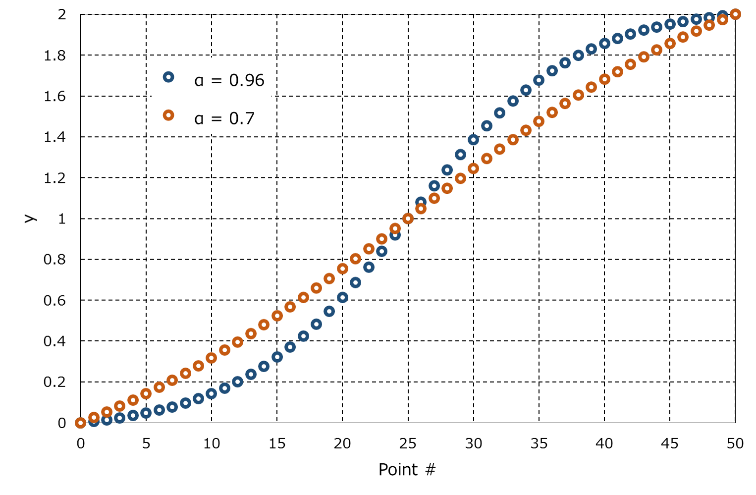
\begin{equation}
y_j = \frac{1}{\alpha}{\rm tanh} \left[\xi_j {\rm tanh}^{-1}\left(\alpha\right)\right] + 1\;\;\;\left( j = 0, …, N_2 \right), \tag{1}
\end{equation}
with
\begin{equation}
\xi_j = -1 + 2\frac{j}{N_2}, \tag{2}
\end{equation}
where \(\alpha\) is an adjustable parameter of the transformation \((0<\alpha<1)\) and \(N_2\) is the grid number of the direction. As shown in the following figure, the grids are more clustered towards the both ends as the parameter \(\alpha\) approaches 1.
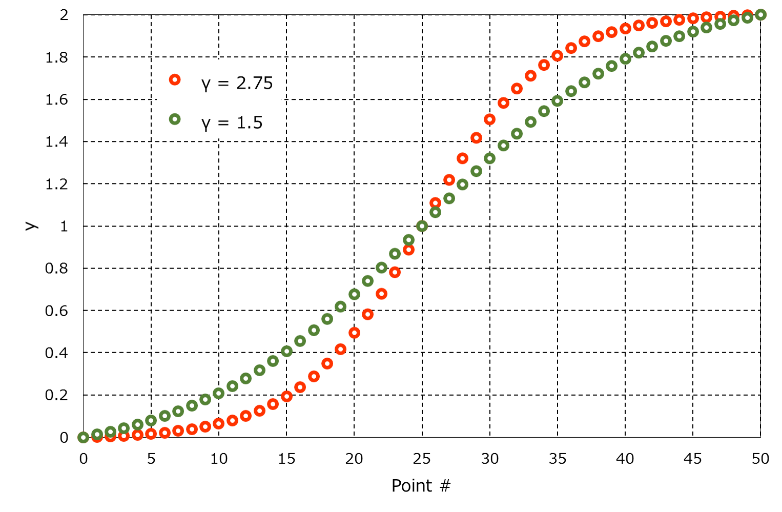
| Example #2 [2] |
\begin{equation}
y_j = 1 -\frac{{\rm tanh}\left[ \gamma \left( 1 – \frac{2j}{N_2} \right) \right]}{{\rm tanh} \left( \gamma \right)}\;\;\;\left( j = 0, …, N_2 \right), \tag{3}
\end{equation}
where \(\gamma\) is the stretching parameter and \(N_2\) is the number of grid points of the direction.
| Grid Images |
Coming soon.
| References |
[1] H. Abe, H. Kawamura and Y. Matsuo, Direct Numerical Simulation of a Fully Developed Turbulent Channel Flow With Respect to the Reynolds Number Dependence. J. Fluids Eng 123(2), 382-393, 2001.
[2] J. Gullbrand, Grid-independent large-eddy simulation in turbulent channel flow using three-dimensional explicit filtering. Center for Turbulence Research Annual Research Briefs, 2003.