Computational Aeroacoustics (CAA)

Gallery
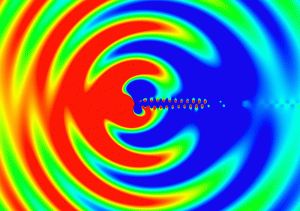
  • Aeolian Tone (Click the image to start animation 🙂 )

aeoliantone

Post Series
  • Part1
  • Part2
  • Part3
  • Blade-Vortex Interaction (BVI) Noise
  • generated by pressure fluctuations near the blade leading edges due to their interactions with the previously generated tip vortices

Open-Source Software for Acoustics Simulation

Coming soon.

Non-reflecting Boundary Conditions in OpenFOAM
Utilities in OpenFOAM
  • probes (Function Objects)
  • noise
Case Research

Explanation of fvOptions in OpenFOAM


The fvOptions functionality in OpenFOAM is flexible framework to add various source terms to the governing equations without the need to rewrite the original source code. The available options in the latest versions of OpenFOAM (v4.0 and v1606+) are listed below.

My explanations are available for the options shown in red.

I’ll extend the coverage.

Available Options

General Sources:


Pressure Gradient Sources:

  • meanVelocityForce:

    to adjust the average velocity in the whole domain or user-specified cellZone or cellSet to the desired value Ubar by adding a momentum source

  • [3.0+] directionalPressureGradientExplicitSource

Heat Exchanger Sources:


Buoyancy Sources:

  • buoyancyForce:

    to add the gravitational force term \(\rho\boldsymbol{g}\) to the momentum conservation equation in XiFoam, reactingFoam and rhoReactingFoam

  • buoyancyEnergy:

    to add the work done by gravitational force \(\rho(\boldsymbol{u} \cdot \boldsymbol{g})\) to the energy conservation equation


Porosity Sources:


Acceleration Source:


Phase Change Source:


Acoustic Damping Source:

  • [1606+] acousticDampingSource:

    to damp the acoustic waves before they reach the boundaries by adding a momentum source term in a buffer region so that the solution will not be contaminated by the reflected waves from the boundaries


Other Sources:


Solver Robustness:


Set Value:

How to Set Source Region

When specifying a source term using fvOptions in OpenFOAM, we can select the selectionMode (how to set the source region) from the following four options:

  • points
  • cellSet
  • cellZone
  • all

The meanings of these options are described in this post.


Recent changes in the basics of the OpenFOAM solvers

constrainHbyA

Comment by Henry G. Weller:

The boundary conditions of HbyA are now constrained by the new “constrainHbyA” function which applies the velocity boundary values for patches for which the velocity cannot be modified by assignment and pressure extrapolation is not specified via the new
“fixedFluxExtrapolatedPressureFvPatchScalarField”.

The member function assignable() is defined in the abstract base class of boundary conditions (fvPatchField):

It is overridden in the basic boundary condition classes (fixedValue, mixed, directionMixed and sliced):

fvc::flux and dotInterpolate

Comment by Henry G. Weller:

surfaceInterpolationScheme: Added dotInterpolate member-function

dotInterpolate interpolates the field and “dots” the resulting face-values with the vector field provided which removes the need to create a temporary field for the interpolate. This reduces the peak storage of OpenFOAM caused by the divergence of the gradient of vector fields, improves memory management and under some conditions decreases run-time.

This development is based on a patch contributed by Paul Edwards, Intel.

constrainPressure

In the case of compressible flow, the following relation \eqref{eq:1} holds for the velocity on the face:
\begin{equation}
\rho \boldsymbol{U}_f \cdot \boldsymbol{S}_f = \left(\frac{\rho \boldsymbol{H}}{A_p}\right)_f \cdot \boldsymbol{S}_f\;-\;\left(\frac{\rho}{A_p}\right)_f (\nabla p)_f \cdot \boldsymbol{S}_f. \tag{1} \label{eq:1}
\end{equation}
Thus
\begin{equation}
(\nabla p)_f \cdot \boldsymbol{n}_f = \frac{1}{|\boldsymbol{S}_f|\left(\frac{\rho}{A_p}\right)_f} \left(\left(\frac{\rho \boldsymbol{H}}{A_p}\right)_f \cdot \boldsymbol{S}_f\;-\;\rho \boldsymbol{U}_f \cdot \boldsymbol{S}_f \right). \tag{2} \label{eq:2}
\end{equation}
The fixedFluxPressure boundary condition calculates the boundary normal gradient of the pressure field using the Eq. \eqref{eq:2} so that the boundary fluxes satisfy the Eq. \eqref{eq:1}.

New collateTimes option in EnSight surface writer

OpenFOAM® v3.0+ Release note:

Many function objects and sampling utilities are able to export field data. In earlier versions of OpenFOAM, the surface data file contained both the geometry and field data. For transient data output, this leads to the geometry being written multiple times, even if it remains static.
In this release, surfaceWriter with Ensight format has been re-written to allow the geometry to be written only once. To enable this feature, a new option collateTimes has been added.

The structures of the postProcessing directory are different with and without the collateTimes option as shown below.

  • collateTimes true

  • collateTimes false


selectionMode of fvOptions in OpenFOAM

When specifying a source term using fvOptions in OpenFOAM, we can select the selectionMode (how to set the source region) from the following four options:

  • points
  • cellSet
  • cellZone
  • all

These options are defined in the cellSetOption class along with the other common parameters among the fvOptions such as timeStart and duration. Let’s check out the meaning of each option along with its source code.

selectionMode 1: points

In this case, we specify some points as shown in the following example. The source region consists of the individual cells that contain the specified points.

  • Example of description

  • Source code

selectionMode 2: cellSet

In this case, we preliminarily create a cellSet corresponding to the source region using OpenFOAM’s utilities such as setSet and specify the created cellSet name.

  • Example of description

  • Source code

selectionMode 3: cellZone

In this case, we preliminarily create a cellZone corresponding to the source region using OpenFOAM’s utilities such as setSet and specify the created cellZone name.

  • Example of description

  • Source code

selectionMode 4: all

The source region is the entire computational domain.

  • Example of description

  • Source code

My Popular Posts on CFD Online

Machine Learning in Fluid Dynamics (To be updated)

I have considerable interest in the application of machine learning techniques to (computational) fluid dynamics. I’ll collect the related information and enhance the following links.

News
Turbulence Modeling

Karthik Duraisamy, A Framework for Turbulence Modeling using Big Data

Anand Pratap Singh et al., Machine Learning-augmented Predictive Modeling of Turbulent Separated Flows over Airfoils

Computer Graphics

Lubor Ladicky et al., Data-driven Fluid Simulations using Regression Forests

  • Convolutional Network (ConvNet)

Jonathan Tompson et al., Accelerating Eulerian Fluid Simulation With Convolutional Networks

Impinging Jet part1

Jet flows can be classified in terms of

  • the flow conditions (laminar and turbulent)
  • the existence of objects: free jet and impinging jet
  • the differences of physical properties between a projected fluid and an ambient fluid: submerged jet and unsubmerged jet
  • the geometry of a nozzle: round jet and slot jet

and so on.

Free Jet

The following video visualizes the flow pattern of a submerged free jet (created by Bjarke Ove Andersen and Mathies Hjorth Jensen of Technical University of Denmark):

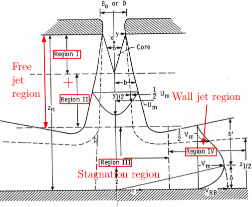
Flow Regions of Impinging Jet [1, 2]

impinging_jet_regions

  • Region Ⅰ is the region of flow establishment. It extends from the nozzle exit to the apex of the potential core. The so-called potential core is the central portion of the flow in which the velocity remains constant and equal to the velocity at the nozzle exit.
  • Region Ⅱ is a region of established flow in the direction of the jet beyond the apex of the potential core; it is characterized by a dissipation of the centerline jet velocity and by a spreading of the jet in the transverse direction.
  • Region Ⅲ is that region in which the jet is deflected from the axial direction.
  • Region Ⅳ is known as the wall jet region, where the directed flow increases in thickness as the boundary layer builds up along the solid surface.

– Gauntner et al. [1]

References

[1] J. W. Gauntner et al., SURVEY OF LITERATURE ON FLOW CHARACTERISTICS OF A SINGLE TURBULENT JET IMPINGING ON A FLAT’PLATE (accessed 2016-09-04)
[2] T. Dairay, DNS of a turbulent jet impinging on a heated wall (accessed 2016-09-04)
[3] N. ZUCKERMAN and N. LIOR, Jet Impingement Heat Transfer: Physics, Correlations, and Numerical Modeling (accessed 2016-09-04)
[4] Y. M. Chung and K. H. Luo, Unsteady Heat Transfer Analysis of an Impinging Jet (accessed 2016-09-04)
[5] ERCOFTAC Classic Database: Normally-Impinging Jet from a Circular Nozzle

Computational Aeroacoustics (CAA) part3

I’ve looked for some benchmark problems in the computational aeroacoustics (CAA) and found the eight problem categories that the BANC (Benchmark Problems for Airframe Noise Computations) workshop has addressed. This workshop is sponsored by the Aeroacoustics Technical Committee.

  • Inline Tandem Cylinders
  • Minimal 4-wheel Landing Gear (Rudimentary Landing Gear)
  • Partially-Dressed Cavity-Closed Nose Landing Gear (PDCC-NLG)
  • NASA Slat Noise Configuration (30P30N)

We can access the documents that describe the problem statement by clicking on the link at the bottom of each page:

I’ll try some problems using iconCFD and introduce my results.

Related Links