Temperature calculation from energy variables in OpenFOAM


The energy conservation equation is expressed in terms of internal energy \(e\) or enthalpy \(h\) in OpenFOAM and the temperature field is calculated from these solution variables. More precisely, we can specify the energy variable in the energy entry in the thermophysicalProperties file and the available options are the followings:

  • specific sensible enthalpy \(h {\rm [J/kg]}\) (sensibleEnthalpy)
  • specific sensible internal energy \(e {\rm [J/kg]}\) (sensibleInternalEnergy)

If we select the hePsiThermo thermophysical model, the temperature field \(T\) is calculated from the solved energy variable in the following function, where the compressibility \(\psi\), dynamic viscosity \(\mu\) and thermal diffusivity \(\alpha\) are also calculated.

Source Code

The calculation procedure of the temperature field depends on the selected energy variable, so the following THE function accordingly switches the called method.

If we choose the sensible enthalpy as the energy variable, the following THs function is called to calculate the temperature from the sensible enthalpy.

The calculation of the temperature is done iteratively using the Newton-Raphson method.

If the specific heat capacity at constant pressure \(c_p\) is expressed in the form of temperature polynomial function (hPolynomial)
\begin{equation}
c_p(T) = \sum_{i=0}^7 c_i T^i, \tag{1}
\end{equation}
the temperature in the j-th cell \(T_j\) is calculated from the following equation
\begin{equation}
\displaystyle \int_{T_{std}}^{T_j} \left( \sum_{i=0}^7 c_i T^i \right) dT = h_j, \tag{2}
\end{equation}
where \(h_j\) is the sensible enthalpy value in the j-th cell. In general the equation will be nonlinear, the iterative solution technique is implemented.

Compressible Flow Solvers

The above function calculate() is called by rhoPimpleFoam, rhoSimpleFoam and sonicFoam etc. from the line “thermo.correct()” after solving the energy conservation equation EEqn:

After updating the compressibility field \(\psi\), the pressure Poisson equation pEqn is constructed and solved.

The density field \(\rho\) is calculated with updated pressure and compressibility fields.

Summary
Energy variable Function used to calculate temperature
sensible enthalpy THs
absolute enthalpy THa
sensible internal energy TEs
absolute internal energy TEa

Study with great curiosity and let’s see the physical phenomena from a HIGHER point of view!

Interesting News – Vanadium Dioxide Violates the Wiedemann-Franz Law


It is an interesting news on conduction heat transfer.

The new article reports that vanadium dioxide conducts electricity much better than it conducts heat at near room temperature:

Abstract

In electrically conductive solids, the Wiedemann-Franz law requires the electronic contribution to thermal conductivity to be proportional to electrical conductivity. Violations of the Wiedemann-Franz law are typically an indication of unconventional quasiparticle dynamics, such as inelastic scattering, or hydrodynamic collective motion of charge carriers, typically pronounced only at cryogenic temperatures. We report an order-of-magnitude breakdown of the Wiedemann-Franz law at high temperatures ranging from 240 to 340 kelvin in metallic vanadium dioxide in the vicinity of its metal-insulator transition. Different from previously established mechanisms, the unusually low electronic thermal conductivity is a signature of the absence of quasiparticles in a strongly correlated electron fluid where heat and charge diffuse independently.

Wiedemann–Franz(-Lorenz) Law

In solids, heat is transported by vibrations of the solid lattice (Phonon contribution) and motion of free electrons (Electronic contribution). In metals, thermal energy transport by electrons predominates. Thus, good electrical conductors are also good thermal conductors as the Wiedemann–Franz law states that:
\begin{equation}
\frac{\lambda}{\sigma} = LT \tag{1}
\end{equation}

  • \(\lambda\): thermal conductivity
  • \(\sigma\): electrical conductivity
  • \(T\): absolute temperature
  • \(L\): Lorenz number (\(=2.45 \times 10^{-8}\)) [\({\rm W}\Omega/{\rm K}^2\)]

The news reports that vanadium dioxide does not obey this empirical law.

Related Topics and Refereces (Japanese)

Thermal Boundary Conditions in OpenFOAM


Many thermal boundary conditions are available in OpenFOAM.
I will upload some basic cases that explain the usage of these boundary conditions.

Source Code
src/TurbulenceModels/compressible/turbulentFluidThermoModels/derivedFvPatchFields/

  • convectiveHeatTransfer

    It calculates the heat transfer coefficients from the following empirical correlations for forced convection heat transfer:
    \begin{eqnarray}
    \left\{
    \begin{array}{l}
    Nu = 0.664 Re^{\frac{1}{2}} Pr^{\frac{1}{3}} \left( Re \lt 5 \times 10^5 \right) \\
    Nu = 0.037 Re^{\frac{4}{5}} Pr^{\frac{1}{3}} \left( Re \ge 5 \times 10^5 \right) \tag{1} \label{eq:NuPlate}
    \end{array}
    \right.
    \end{eqnarray}
    where \(Nu\) is the Nusselt number, \(Re\) is the Reynolds number and \(Pr\) is the Prandtl number.

  • externalCoupledTemperature
  • externalWallHeatFluxTemperature

    This boundary condition can operate in the following two modes:
    Mode#1 Specify the heat flux \(q\)
    \begin{equation}
    -k \frac{T_p – T_b}{\vert \boldsymbol{d} \vert} = q + q_r \tag{2} \label{eq:fixedHeatFlux}
    \end{equation}
    * \(k\): thermal conductivity
    * \(q_r\): radiative heat flux
    * \(T_b\): temperature on the boundary

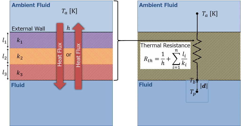
    Mode#2 Specify the heat transfer coefficient \(h\) and the ambient temperature \(T_a\) (Fig. 1)
    \begin{equation}
    -k \frac{T_p – T_b}{\vert \boldsymbol{d} \vert} = \frac{T_a – T_b}{R_{th}} + q_r \tag{3} \label{eq:fixedHeatTransferCoeff}
    \end{equation}
    * \(R_{th}\): total thermal resistance of convective and conductive heat transfer
    \begin{equation}
    R_{th} = \frac{1}{h} + \sum_{i=1}^{n} \frac{l_i}{k_i} \tag{4} \label{eq:Rth}
    \end{equation}

    Figure 1
  • fixedIncidentRadiation
  • lumpedMassWallTemperature

    There is a dimensionless quantity called the Biot number, which is defined as
    \begin{equation}
    Bi = \frac{l/k}{1/h} = \frac{hl}{k}, \tag{5} \label{eq:Biot}
    \end{equation}
    where \(h\) is the heat transfer coefficient, \(k\) is the thermal conductivity of a solid and \(l\) is the characteristic length of the solid. As the definition in Eq. \eqref{eq:Biot} indicates, it represents the ratio of the internal conduction resistance \(l/k\) and the external convection resistance \(1/h\). If the Biot number is small (\(Bi \ll 1\)), the solid may be treated as a simple lumped mass system of an uniform temperature. This boundary condition calculates the uniform temperature variation \(\Delta T\) on the boundary from the following equation:
    \begin{equation}
    m c_p \Delta T = Q \Delta t. \tag{6} \label{eq:lumpedmass}
    \end{equation}
    * \(m\): total mass [kg]
    * \(c_p\): specific heat capacity [J/(kg.K)]
    * \(Q\): net heat flux on the boundary [W]
    * \(\Delta t\): time step [s]

  • outletMappedUniformInletHeatAddition
  • totalFlowRateAdvectiveDiffusive
  • wallHeatTransfer
  • compressible::thermalBaffle1D
  • compressible::turbulentHeatFluxTemperature
  • compressible::turbulentTemperatureCoupledBaffleMixed
  • compressible::turbulentTemperatureRadCoupledMixed
  • compressible::alphatJayatillekeWallFunction
  • compressible::alphatPhaseChangeWallFunction
  • compressible::alphatWallFunction

Filter Width – maxDeltaxyz


Several options are available in OpenFOAM for calculation of the filter width used in the large eddy simulation (LES) and detached eddy simulation (DES). In this blog post, the maxDeltaxyz option is covered in some detail.

OpenFOAM Version: OpenFOAM-dev, OpenFOAM v1612+

Implementation in OpenFOAM

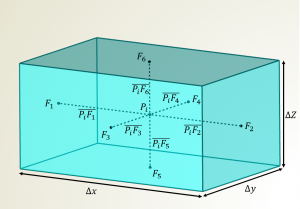
The maxDeltaxyz option calculates the filter width of the \(i-\)th cell \(\Delta_i\) by taking the maximum distance between the cell center \(P_i\) and each face center \(F_j\)
\begin{equation}
\Delta_i = {\rm deltaCoeff} \times \max_{1 \le j \le n_i} \left\{ \overline{P_iF_j} \right\}, \tag{1} \label{eq:deltaxyz}
\end{equation}
where \({\rm deltaCoeff}\) is a constant of proportion (user input) and \(n_i\) is the number of the faces of the \(i-\)th cell.

Fig. 1 Graphical illustration for the case of a regular hex cell.

For a regular hexahedral cell shown in Fig. 1, the computed \(\Delta\) using Eq. \eqref{eq:deltaxyz} equals one-half of the maximum cell width \(\Delta x\), so the deltaCoeff coefficient should be set to 2 in the turbulenceProperties file as shown below.

The filter width is calculated in the following function.

Implementation in OpenFOAM v1612+

In OpenFOAM v1612+, the face normal vectors are considered in order to take into account the mesh non-orthogonality.

Some comments

This definition \eqref{eq:deltaxyz} is often used in the detached eddy simulation (DES) where some anisotropic grid cells such as “book”, “pencil” and “ribbon”-shaped cells exist in a boundary layer mesh. The position where switching between the RANS and LES modes occurs in the DES97 model [1] depends on how to calculate the filter width \(\Delta\)
\begin{equation}
\tilde{d} \equiv {\rm min}\left( d, C_{DES}\Delta \right), \tag{2} \label{eq:dTilda}
\end{equation}
where \(d\) is the distance to the closest wall and \(C_{DES}\) is a calibration constant.
Several modified length scales have been developed to prevent a delay of the Kelvin-Helmholtz instability in free and separated shear layers [2].

References

[1] P. R. Spalart, W.-H. Jou, M. Strelets and S. R. Allmaras, Comments on the feasibility of LES for wings, and on a hybrid RANS/LES approach. 1st AFOSR Int. Conf. on DNS/LES, Aug. 4-8, 1997, Ruston, LA. In “Advances in DNS/LES”, C. Liu and Z. Liu Eds., Greyden Press, Columbus, OH.
[2] P. R. Spalart, Detached-Eddy Simulation. Annu. Rev. Fluid Mech. 41, 181-202, 2009.

32th TSFD Symposium

第32回生研TSFD (Turbulence Simulation and Flow Design) シンポジウム 「乱流シミュレーションと流れの設計 -数値計算による熱流体現象の理解、予測、制御」 が,2017年3月22日(水) に東京大学生産技術研究所 (駒場IIリサーチキャンパス) において開催されるそうです.プログラム等はまだ未確定ですが,ぜひ勉強してきたいと思います.

URL:
http://www.iis.u-tokyo.ac.jp/~tsfd2017/

WALE SGS model in OpenFOAM

Last Updated: May 6, 2019

The WALE (Wall-Adapting Local Eddy-viscosity) SGS model is one of the major SGS models. It is an algebraic eddy viscosity model (0-equation model) as with the Smagorinsky SGS model, but it has some excellent features that the Smagorinsky model does not have.

Implementation in OpenFOAM

In the WALE model, the subgrid scale eddy viscosity \(\nu_{sgs}\) is evaluated as
\begin{equation}
\nu_{sgs} = C_{k} \Delta \sqrt{k_{sgs}}, \tag{1} \label{eq:nusgs}
\end{equation}
where \(C_{k}\) is a model constant and \(k_{sgs}\) is the subgrid scale kinetic energy. You can find its definition in this post.

The traceless symmetric part of the square of the velocity gradient tensor \(S^d\) is calculated in the following function.
\begin{eqnarray}
S_{ij}^d = \frac{1}{2} \left( \frac{\partial \overline{u}_k}{\partial x_i}\frac{\partial \overline{u}_j}{\partial x_k} + \frac{\partial \overline{u}_k}{\partial x_j}\frac{\partial \overline{u}_i}{\partial x_k} \right) – \frac{1}{3} \delta_{ij} \frac{\partial \overline{u}_k}{\partial x_l}\frac{\partial \overline{u}_l}{\partial x_k}, \tag{2} \label{eq:sd}
\end{eqnarray}
where \(\delta_{ij}\) is the Kronecker delta.

These tensor operations used above are summarized in the following post:

The subgrid scale kinetic energy \(k_{sgs}\) is
\begin{equation}
k_{sgs} = \left( \frac{C_w^2 \Delta}{C_k} \right)^2 \frac{\left( S_{ij}^d S_{ij}^d \right)^3}{\left( \left( \overline{S}_{ij} \overline{S}_{ij} \right)^{5/2} + \left( S_{ij}^d S_{ij}^d \right)^{5/4} \right)^2}, \tag{3} \label{eq:ksgs}
\end{equation}
where
\begin{equation}
\overline{S}_{ij} = \frac{1}{2} \left( \frac{\partial \overline{u}_{i}}{\partial x_{j}} + \frac{\partial \overline{u}_{j}}{\partial x_{i}}\right), \tag{4} \label{eq:s}
\end{equation}
is the resolved-scale strain rate tensor.

Finally, we can get the following expression by substituting Eq. \eqref{eq:ksgs} into Eq. \eqref{eq:nusgs}:
\begin{eqnarray}
\nu_{sgs} = \left( C_w \Delta \right)^2 \frac{\left( S_{ij}^d S_{ij}^d \right)^{3/2}}{\left( \overline{S}_{ij} \overline{S}_{ij} \right)^{5/2} + \left( S_{ij}^d S_{ij}^d \right)^{5/4}}, \tag{5} \label{eq:nusgs2}
\end{eqnarray}
It is the same as Eq. (13) in [1].

Features
  • Algebraic eddy viscosity model (0-equation model)
  • The rotation rate is taken into account in the calculation of \(\nu_{sgs}\)
  • To be able to handle transition
  • Damping is Not necessary for \(\nu_{sgs}\) in the near-wall region
References

[1] F. Nicoud and F. Ducros, Subgrid-scale stress modelling based on the square of the velocity gradient tensor. Flow, Turbulence and Combustion, 62(3), 183-200, 1999.

Final expression of the SGS eddy viscosity is relatively simple and the implementation into OpenFOAM is not so complicated but the process of deriving the expression described in [1] is not easy to understand. I want to develop my SGS model someday 🙂

Thanks 2016!

Thank you very much for visiting my page and sending encouragement messages.

I launched this blog this year and I’m glad that many visitors all over the world have read my posts.

map_visitors

I’m going to continue this blog next year. Additionally, I want to collaborate with many contributors all over the world to create a synergy effect and provide more useful, reliable and accurate information.

Have a happy New Year!
Fumiya

Some Topics of My Interest on (Computational) Fluid Dynamics


I will accumulate more and more information of some topics of interest in the field of fluid dynamics. When I get a better understanding about the following topics, I will prepare dedicated pages.

Physical mechanism of energy cascade

I want to understand the physical mechanism of the energy cascade in turbulent flows and have found some useful references:

If you have any other information on this subject, could you inform me of the current status of research?

Boundary layer flow

I found a very informative and beautiful video of a spatially developing turbulent boundary layer on a flat plate.
A video is worth ten thousand words!


Video credit: J. H. Lee, Y. S. Kwon, N. Hutchins and J. P. Monty

As we can see, the turbulent boundary layer becomes thinner and the eddies are smaller in the higher Reynolds number \(Re_{\tau}\) case. The Reynolds number \(Re_{\tau}\) based on friction velocity \(u_{\tau}\) is often used in studies of wall-bounded turbulence, e.g., the turbulent channel flow.

Wall-Modeled Large Eddy Simulation

TTT Technical Highlight: Wall-Modeled Large Eddy Simulation of High Reynolds Number Flows

I will add topics and update information regularly!